New TR-909 display module
I am currently in the process of buildning a replica of the classic Roland TR-909 drum machine. The replica is called Din Sync RE-909, and it is a very faithful reproduction of the original machine.
Almost all parts are interchangeable between the RE-909 and the TR-909. Almost, because some parts are no longer being produced. Examples of this is that the RE-909 uses Cherry MX switches instead of the originals Alps SFKLs. The RE uses different tactile switches with built-in LEDs and the RE has support for a LED-display currently in production in addition to the display module from the original machine.
This brings us closer to the topic of this article because I don't think the modern LED-display looks the part. The edges of the digits have the wrong shape. The background has the wrong colour. It does not come with a colour filter. All of this is, of course, unacceptable.
Let's do something about it!
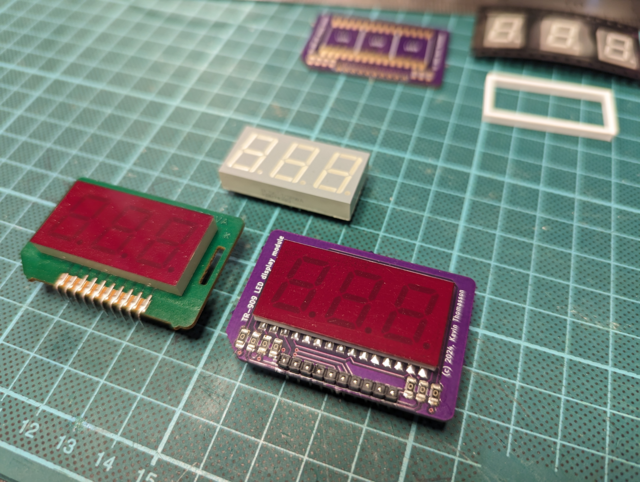 Original TR-909 display to the left, the display from RE-909 BOM on top and my display module to the right
The search for an alternative display
It all started when I discovered that the edges of the numbers did not have the same shape as on the original display module—and what is once seen cannot be unseen.
I began by searching for compatible displays on AliExpress and eBay as a drop-in replacement of the one in the BOM (Bill Of Materials). Several modules having the correct size (0.56") that seemed to have the right shape and colour of the LEDs were available. I started by ordering two different variants. When they arrived a few weeks later, it turned out that the store had shown an incorrect image and that the shape of the numbers was exactly the same as the display in the BOM. Bad luck, I thought, so I tried ordering from other sellers only to have the exact same thing happen again.
Can I make my own display module?
With over 20 displays useless for this application I began exploring the possibility of creating my own module on a PCB. If I could make my own module, I would be able to use a wider array of displays which aren't necessarily pin-compatible with the one in the BOM. It would also open up the possibility of using displays with only one digit and combine three of them.
All through-hole component displays I could find were too tall to fit in the chassis with the added height of a daughter PCB. At least on an original TR-909, and I want the module to be a drop-in replacement on both the TR and the RE.
SMT it is! I settled for Würth Elektronik "WL-S7DS 7 SEGMENTS DISPLAY SMT S", DigiKey product number 732-157143S12700CT-ND.
PCB design
Now that I had the display components physical dimensions clear to me I needed to figure out what the layout and size of the circuit board would be.
Luckily I have an original Roland TR-909 that I can use as a reference so I desoldered the display module from the TR. After this I did some measurements using a caliper and took some high resolution pictures of the module. Using this information I was able to decide the position of the display components and the dimensions of my PCB.
The pinout of the original module was easy to "beep out" using a multimeter as the RE-909 have footprints for both the modern display and the original module. All I had to do was look in the datasheet for the display in the BOM for the RE to find out what the pins do.
I decided to add resistors to the display module making it possible to match the brightness of the LEDs on a vintage machine without the need for changing any resistors on the original board. All to avoid the risk of damaging traces when desoldering and soldering.
All my previous PCB designs have been made using Autodesk Eagle, but I wanted to try out KiCad this time. Just out of curiosity.
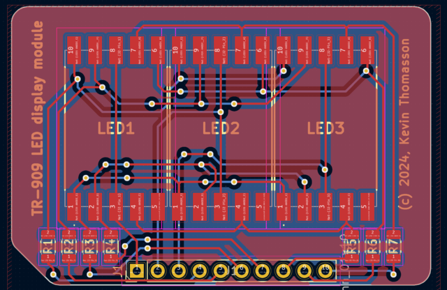 PCB design finished in KiCad
When the design was finished I was too lazy to etch a double sided prototype board at home, so I ordered some nice purple PCBs from Oshpark using their prototype service. I have used their services before with exellent results, and they did not dissapoint me this time either.
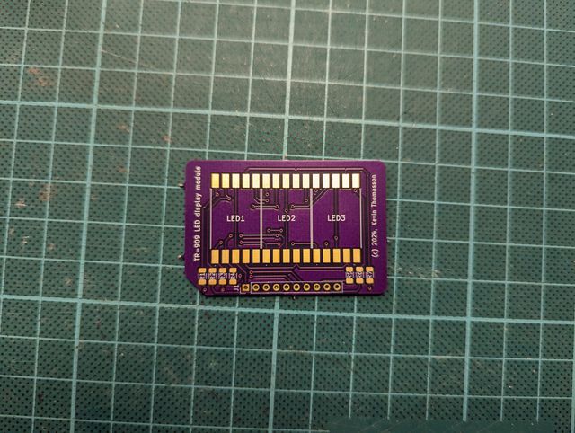 Printed circuit board
Assembling the board
I started by soldering the 1206 size resistors. In my case, I chose to use 0 ohm jumpers for my RE-909. It had been a while since I had reason to use my hot air station, so now I had the opportunity to do some practice.
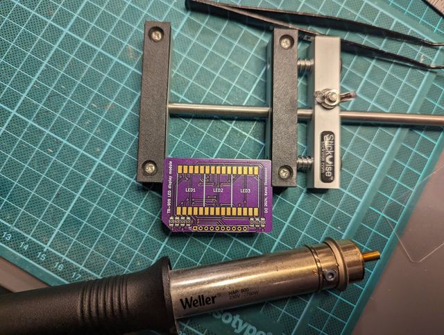 SMD resistors soldered
Since I now had chosen to use 7-segment displays with only one digit, I had to find a way to line them up perfectly on the board in preparation for soldering. When I tried laying the displays out by hand, I found that the margin around the digit itself was smaller than on the original display module. What a disaster!
Post mental breakdown, I had an idea! If I could 3D-print a frame in the same colour as the plastic in the display, I could also use the frame to position the displays straight. I bought the whitest PLA filament I could find and tried it out. After some filing on the inside of the corners, the 7-segment displays fit snugly in the frame.
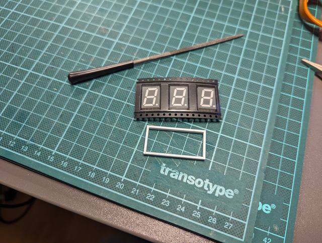 SMD 7 segment LEDs and 3D-printed frame
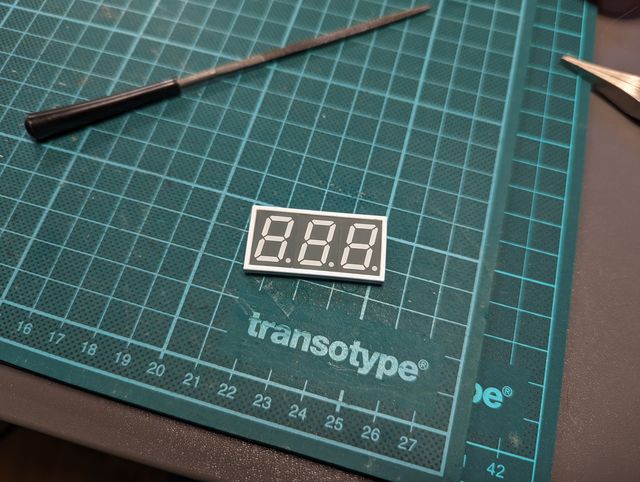 SMD 7 segment LEDs installed in frame
With the displays positioned perfectly straight in the frame, I attached a piece of double-sided adhesive tape on the back side to temporarily affix the displays to the PCB.
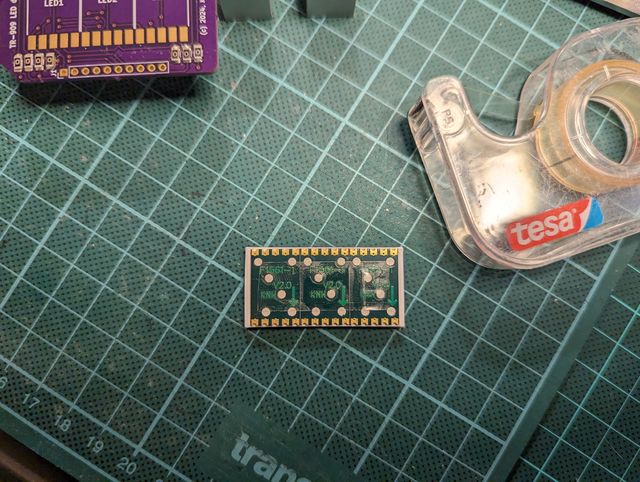 Double sided adhesive tape applied to backside
After carefully positioning the displays correctly, it was just a matter of soldering them on. For this I chose to solder the displays with my soldering iron instead of using the hot air station as capillary action would have ruined the positioning and probably melted the tape.
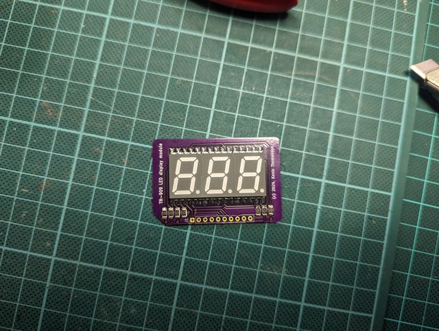 7 segment LEDs soldered to the PCB
Preparation of the display surface
In order for the display to have the correct appearance, the background colour had to be removed. To remove the paint, I started by gluing the frame to the display a very small amount of super glue.
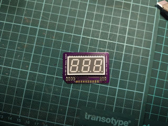 3d printed frame fitted on soldered board
Then the frame and display had to be sanded level, removing the paint in the process. I used 200 grit, followed by 600 grit wet sandpaper. It is important to use wet sandpaper not to melt the 3D-printed PLA frame.
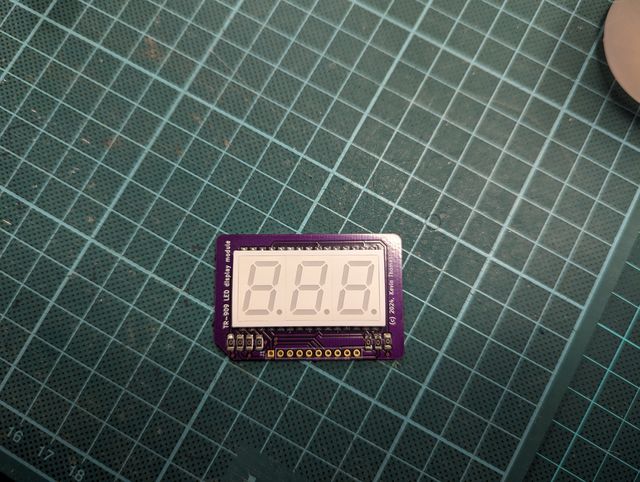 Display and fame sanded level
When the display and the frame was sanded perfectly level and all the paint was gone, I found that you could see small gaps between the frame and the display as well as between the display elements. This was not good enough—something had to be done.
I tried dabbing white acrylic paint over the entire surface of the display. After I let it dry completely, I used the same sandpaper as before to remove the paint, but this time without water since the paint is water based. As I didn't use water when sanding down the layer of paint, I used very little force and let the process take its time. I repeated this paint and sand process two times over.
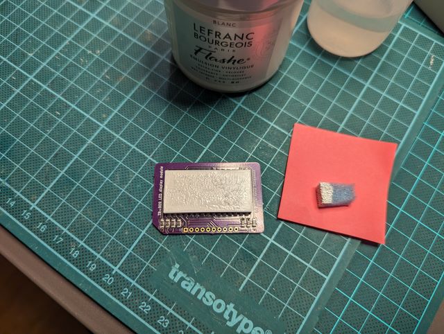 White acrylic paint added on top of sanded surface
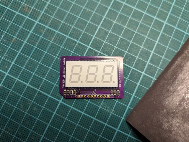 Acrylic paint sanded down
The result speaks for itself. It looks even better in real life!
The colour filter
It was not an easy task to find a colour filter for the display. To begin with, I searched for a plastic film in the correct colour with a thickness of 0.3 mm, same as the original. I found a package of 0.3mm film in a variety of colours on Amazon, which I ordered, but the red colour was not deep enough. I also bought some red film from a hobby store that I thought looked about right on my computer screen. That film had the same problem.
The plastic film I needed didn't seem to be available anywhere. I needed to drop some requirement to find what I needed. The colour was paramount but the thickness was not.
I found out that photo studios uses very thin coloured films to achieve different light effects, and they are available in a large number of colours. I ordered some in a colour named primary red. When the plastic film arrived, I was pleasantly surprised that the colour was very close to the display module from my TR-909. Definitely close enough.
I tried attaching it to one of my 20, until now useless, displays with double-sided tape as a test. The film became all wrinkled. I thought it was probably due to the double sided tape. Then I tried to use a glue pen instead. Same problem again. The film was too thin and I could not find any thicker film in a acceptable colour. Why was I even doing this? Didn't I have anything more sensible to do with my time?
Apparently, I did not, because a few days later I came up with the idea to test the film in my laminator. I was unsure if the film would stick to the laminator pouch, but it did. Yes! I was in business again.
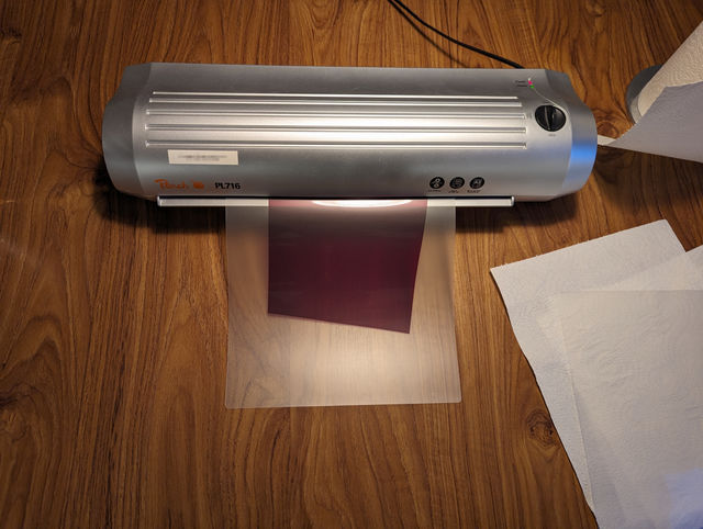 Colour filter in laminating machine
In order to cut the laminate to the correct size, I printed a template on regular paper which I then glued to the laminate using a glue stick on a nice and clear spot.
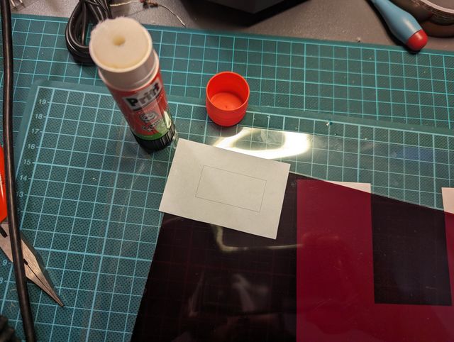 Printed out template temporarily glued to the laminate
I cut the laminate to size using a breakaway knife and a steel ruler. When done, I rinsed the laminate in water, releasing the paper template. Finally I used some washing-up liquid to clean it from fingerprints and any dust.
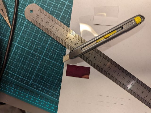 Laminate cut to the correct size
Now I had to get the laminate to adhere to the display itself without ruining the transparency. Uniformly. As it turned out, this was not an easy thing to do.
I tried different methods ranging from double sided adhesive tape, several types of glue that I dabbed on (I even tried using sugar water out of desperation) to spray glue. The problem with all methods was that dark spots developed where the glue had too much contact with both surfaces.
Then I tried to use a very thin coating of 3M 77 spray glue. No spots. Permanently fixed!
I had to use the spray adhesive approximately 40 cm above the display and move my hand about as fast as when you wave your hand to someone very far away. Resisting the urge to go a bit slower over the display.
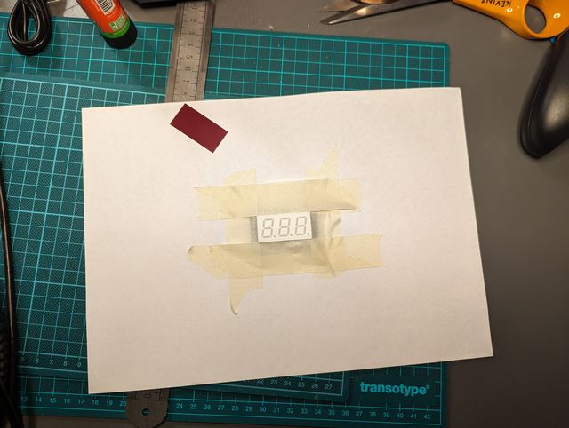 Display prepared for spray glue application
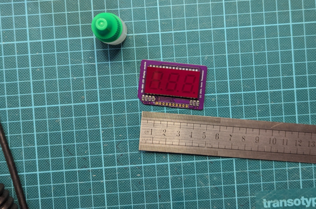 Finished result
In closing
This project took much longer than I imagined it would take when I started, and perhaps that is a good thing, because otherwise I maybe never would have bothered.
It takes a significant amount of work to make a display module from start to finish, but if I get the hang of it, maybe I'll make small batches of display modules that I can sell. However, they will certainly not be cheap considering all the manual labor and materials involved.
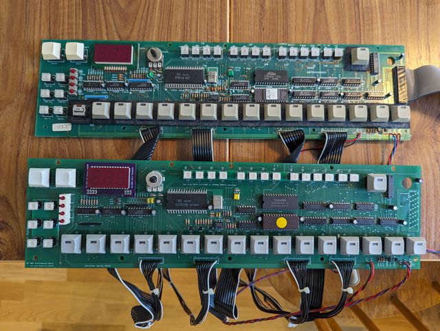 Glamour shot. TR- and RE-909 switchboards.
Comments
Martin
Your result looks great! Any chance you can share your kicad, 3d print files and link to coloured film? Just in case I find some time :)